2. Acoustic performance parameters
2.1 Sound absorption performance
The tip provided for mounting satisfies the sound absorption coefficient at the cutoff frequency of 0.99 (take the cutoff frequency of 125 Hz as an example)
Frequency (Hz) sound absorption coefficient
125 0.99
250 0.99
500 0.99
1000 0.99
2000 0.99
4000 0.99
8000 0.99
2.2 noise reduction performance
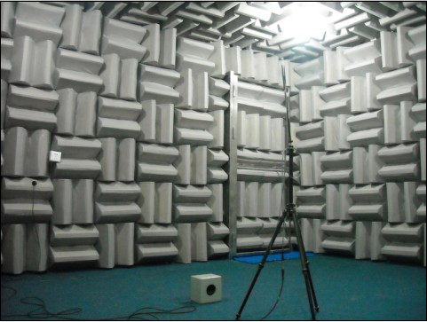
The semi-anechoic chamber can provide an approximate semi-free field environment with a frequency range from 125 Hz to 8000 Hz. The inverse square law performance deviation meets the requirements of the following international standards ISO 3745, .ANSI S12.55 and GB 6882:
The measurement requirement is to use a single frequency signal, which is selected at the center frequency of 1/3 octave.
2.3 acoustic isolation performanceThe sound insulation characteristics of the semi-anechoic chamber are determined according to the design requirements and the surrounding environment.Thunderstar anechoic technology,Inc ’s patented technology of "Turbocharged Micro-Circulation Inverter Noise Reduction Ventilation System" (Patent No.: 200520108948.5) can meet the following sound insulation characteristics:
Octave (Hz) 125 250 500 1000 2000 4000 8000
Transmission loss(dB) 28 31 39 48 54 58 63
Third, semi-anechoic chamber components
3.1 Professional sound-absorbing tip material (Patent No.: 200720155131.2)
Sampling super green environmentally friendly sound absorbing cotton, the surface is glued and cured. Dust-proof technology is applied between the glass wool and the finish to make the sharp surface easy to clean, ensuring long-term stable acoustic performance parameters.
3.2 Tips (Patent No.: 200920279477.2)
The pointed door adopts a metal perforated sound-absorbing tip structure, which makes the pointed door and the internal tip form a complete sound absorbing surface. The pointed door adopts a special hinge to make the door switch easy, long-term deformation, and the tip door is open. It can be designed to be interlaced with the inner wall sharp teeth to save space.
3.3 Sound insulation door (Patent No.: 200920279477.2)
In the design of the anechoic chamber (semi-anechoic chamber), the door is a very important factor. A good sound insulation door should have good sound insulation and optimized edge effects. It adopts 1.5mm thick cold-rolled steel plate, and internally forms sound-absorbing cotton. The hinge adopts imported products, and the whole door floats when the door is opened. The high-density magnetic edge banding is semi-closed when returning to the door, ensuring that its acoustic treatment can be matched with the acoustic treatment of other surrounding components to eliminate edge leakage as much as possible, the strength meets the operational requirements, and the deformation is not used for long-term use, while the outer surface is sprayed. Plastic treatment makes the color consistent with the sharpness.
3.4 interior wall
The structure of the inner wall and ceiling can be designed according to user requirements. The commonly used structures are:
●Concrete structure---This structure has good sound insulation effect, but it has a large weight. High requirements for floating ground.
● "Noise Shield" composite sound insulation structure - patented design, consisting of two layers of steel plate, the inner layer is perforated, and the interlayer is filled with a high sound absorption coefficient sound absorber to ensure the sound insulation effect. Lighter weight, but at a slightly more expensive price.
3.5 floating ground
In the case of high external noise or vibration measurement, the floating structure is usually used to isolate the external influence. The damping material plays a key role in the floating structure. The vibration reduction methods are as follows:
◆ Spring structure: The vibration isolation frequency can be achieved (1Hz, this structure is adopted when the low noise requirement is high. However, the disadvantages are: high cost, difficult maintenance, and rust prevention of the spring.
◆Rubber damping pad structure: The vibration isolation frequency can be achieved (7Hz, this structure is adopted when the low noise requirement is high.
◆ Glass wool felt damping structure: The vibration isolation frequency can be achieved <15Hz, and the structure cost is low.
In actual engineering, what kind of damping is used depends on:
● Required noise floor
● Surrounding environment, noise source and vibration source
Use the original ground on the ground or replace the terrazzo or ground rotation with a sound absorption coefficient less than 0.06.
3.6 Lighting
Incandescent lamps are available to meet indoor lighting. Incandescent lamps require minimal noise and acoustic reflection, as well as consistency and aesthetics of the lamp and the overall interior design.
3.7 Circuit System
In addition to the illuminator, all circuit conduits, wires, and controls are required to be mounted on the tip to avoid acoustic reflections.
3.8 wiring pipeline
The routing pipeline meets the required route and does not affect the test.
3.9 Control room
The design of the control room should take into account the user’s aspects and functions, and the installation of the monitoring system can be chosen to reduce the human impact of the measurement.